

On The Bench: Compressors Part 1
What’s the difference between a FET and a Vari Mu anyway?
5 February 2009
Tutorial: Rob Squire
This issue, I thought I’d head back over to the outboard rack and continue my rambling series examining the ins and outs of audio processors. Back in Issues 61 & 62 I looked at mic preamps and equalisers. This Issue let’s look behind the knobs of the one piece of audio equipment that causes more debate, diatribe and hair pulling than any other – the compressor/limiter.
First up, for the main part I’ll just be referring to compressors – although much of this will also apply to limiters – so for now let’s throw them all into the one basket.
In Issue 61 there was an article examining Andy Page’s mixing of an Alanis Morissette album, wherein an astounding amount of micro-automation of individual wave files was performed. Within very short time frames, automation curves were drawn over waveforms, changing the dynamic shape of individual notes and chords. In a simplified sense, this is compression – changing the volume of a sound in a dynamic fashion and potentially making those changes very quickly. Riding the faders is the time honoured method of dynamic volume control and the technique begs the question; if you had enough fingers and were sufficiently fast and accurate, could you dispense with all your compressors? Certainly with the advent of comprehensive DAW automation, perhaps you now can.
Let’s find out!

WHAT’S A COMPRESSOR?
The first thing to lay bare about all compressors is that they will contain an amplifier, indeed, often a couple of amplifier stages of some design, through which the audio signal is always passing. This could be a modern IC-based amplifier, discrete transistor of Class-A or A/B design, or valves. Throw in audio transformers (or not), and forget what the actual compressor circuit is doing for a moment, and already a sonic stamp is being placed on the audio. When coupled with the type of gain reduction circuit a particular compressor employs, these components (and their deployment) play a significant role in the ‘sound’ of a compressor. Indeed, some engineers pass audio through a unit – such as a Urei 1176 – with the compression disabled, just to add that special something to an audio track.
A compressor must contain some piece of circuitry or device that can affect the gain of a signal passing through it in response to a control signal. The control signal, often called the ‘sidechain’ is simply a second signal derived from the audio feeding through the compressor, in which the time and level-dependent parameters are applied. We thus have two important signal paths in a compressor: the main audio signal, which flows though the gain controlling device and amplifier stage (to buffer the gain device and drive sufficient levels to the unit’s output socket); and the control path, which follows a separate route and ends up in the control input of the gain control device (see Fig. 1).
There are numerous ways to control audio gain or dynamics with a control signal and each imparts a distinct quality on the passing audio.
VARI MU
This is where it all began. The first compressors were all tube and developed exclusively for limiting the maximum audio level into AM radio transmitters. It’s a quirk of AM radio that it’s very bad to over modulate (or over-drive) the transmitter and so fast-acting, high-ratio compression – i.e. limiting – was highly desirable. The earliest valve limiter I’ve been able to reference was an RCA 96-A, certainly manufactured before 1947 and possibly as early as 1941. (In fact, there is one on the shelf behind me… and it looks so damn good, who cares what it sounds like!)
Vari Mu compressors exploit the properties of a particular class of valves, properly called remote cut-off valves, in which the gain of the valve can be widely varied. In a Vari Mu circuit, in order to affect the gain, the control signal is effectively mixed in with the audio signal. This gives rise to the reported thumping that Vari Mu compressors can exhibit. Minimising this effect requires Vari Mu valves to be set up as balanced pairs and often transformer coupled. Indeed, often a number of transformers are used: the AWA G51501, for example, uses four transformers in the audio path to reduce the leakage of the control signal (thumping) through to the output of the unit. This, along with some valve-specific adjustment controls and correctly designing the sidechain, can keep the undesirable thumping effect to negligible levels.

OPTO-METRY
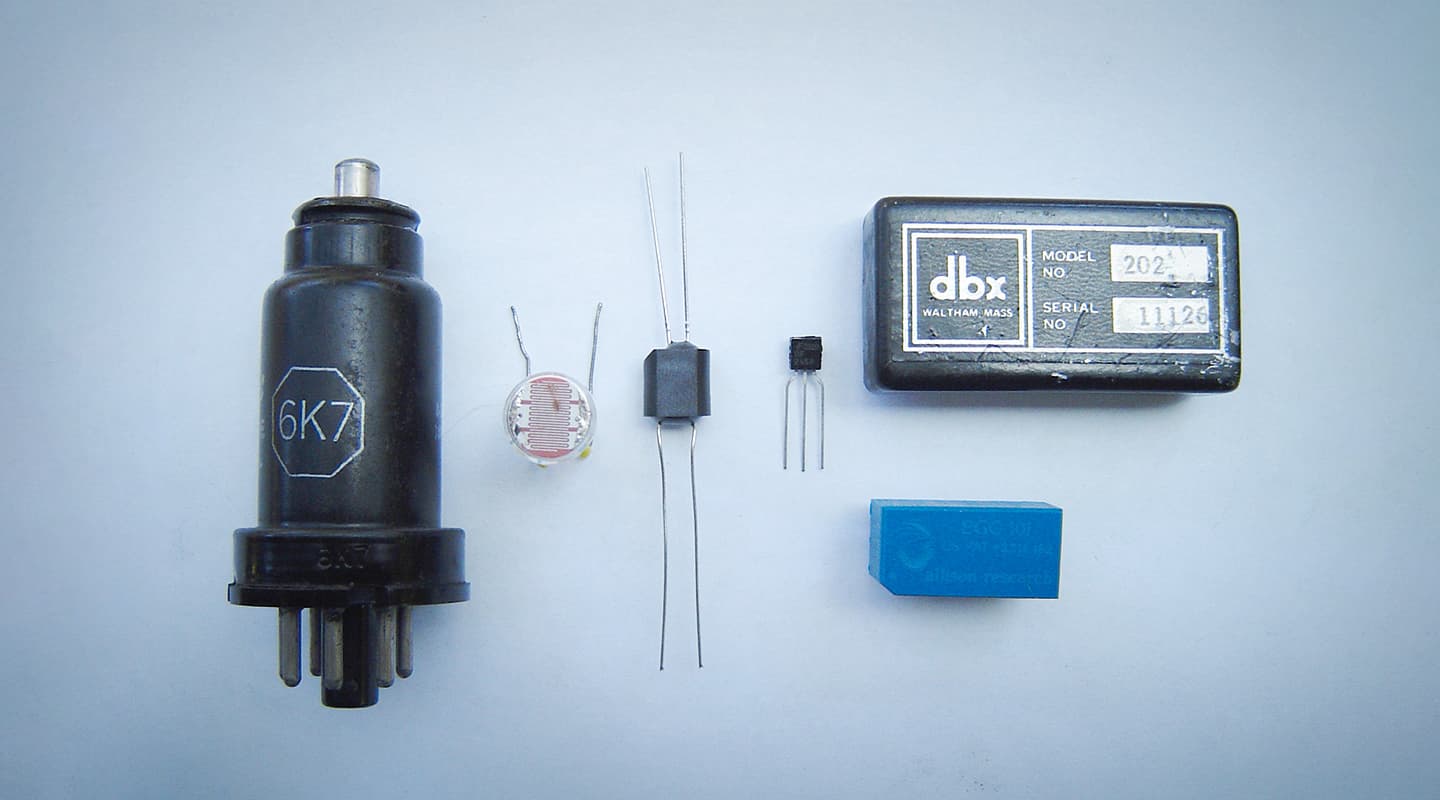
The myth is that Joe Meek invented the Opto compressor by passing audio through one of the newly developed photo-sensitive cells andstrapping a light bulb to it, with the light bulb driven by a split of the audio signal. Opto cells are manufactured from a mixture of materials that essentially create a resistor that’s light sensitive. The resistance can vary from millions of ohms in the dark to a few hundred ohms in bright light. By pairing this light-dependent resistor (LDR) with a fixed resistor, a simple volume control is created, and through control of the brightness of a light source illuminating the LDR, so the audio level can be controlled (see Fig. 2).
Early LDRs were highly non-linear devices with wide variation from one part to another. The variations related to almost all measurable aspects of an LDR’s characteristics – distortion of the audio passing through it, the speed of response to changes in the light level, range and scale of resistance change to a given light variation were all variable from one part to another. For a manufacturer, this is a huge hassle. To a DIYer it’s a lottery. Manufacturers who built LDR-based compressors needed to purchase large quantities of their chosen LDR and grade them on test jigs to find out which ones provided the target qualities they were seeking. An excellent example of this is the Teletronix LA-2A and later the Urei LA-3A in which the entire attack and release characteristics are governed by the chosen opto cell. Sorting through a batch of 100 of these cells may yield 10 within an acceptable range… the rest go in the bin. The non-linear behaviour of LDRs results in a whole bunch of qualities that conspire to make opto compressors unique.
Most LDRs add distortion, for example, with the quantity rising with increasing signal level and often exhibiting a complex change in distortion level as the LDR is illuminated and the gain reduction begins.
In an LA-2A the distortion rises as the unit heads into gain reduction, with the distortion increasing until it finally reaches a peak at around 4dB of gain reduction. After this tipping point the distortion begins to decrease again as the gain reduction continues to increase. The level of distortion can vary widely from unit to unit but can typically reach a peak of 3% of mainly third-order harmonics. Once the unit returns to 0dB of gain reduction the distortion levels very slowly settle back down to their minimum. The complexity of this behaviour and the fact that not all parameters change simultaneously give this particular compressor a very distinctive character.
Then there’s the whole ‘pre-charging’ aspect of opto compressors, whereby their response to incoming audio is affected by what has just taken place. In fact, in the past it was common practice when using an LA-2A during mixdown, to hit the unit with a ‘pre-run’ of the track immediately before committing the mix to tape, such was the difference in the attack behaviour between the response of the compressor hit with audio five minutes ago as opposed to five seconds ago!
Today, modern opto-cells that contain LED-based light-dependent resistors are manufactured to higher tolerances than the original LDRs. Their characteristics are both more predictable and the variation from part to part is small enough for manufacturers to use them without the laborious sorting and grading previously required. Indeed, some are so fast in their response times that controlling the attack and release via the circuitry of the sidechain is now a viable option, and therefore user-adjustable.
With Diode/Zener Bridge designs, any signal going higher than a very tightly defined level will cause quite gross distortion, heading you into fuzz box territory rather than the rolling hills of compressor-land.
COMPRESSOR FET-ISH
In the mid ’60s a new type of transistor became available: the field effect transistor, or FET. Two aspects of the FET interested audio designers: the very high input impedance available and that the device could be made to closely replicate the behaviour of a variable resistor in response to a control voltage. Just like the LDR in opto compressors, the FET coupled with a fixed resistor and a control voltage can behave just like a volume control. The intrinsic advantage of a FET, unlike an LDR, is that is can operate very quickly. Indeed, one of the first FET compressors – the Urei 1176 – boasted a minimum attack time of 20 microseconds, which was much faster than had previously been obtained with Vari Mu and Opto technology.
If FETs have a weakness it’s that they’re hamstrung by how much signal level can be passed through them before distortion rises dramatically. Consequently, all FET compressors typically reduce the incoming audio signal by 20dB before it hits the transistor itself. This level then needs to be ‘made up’ again in the amplifier following the FET, which places an inherent design limitation on the noise performance of any FET compressor. Typically, these compressors have a noise floor of around –70dBu. The naked distortion of a FET is also usually dealt with through a distortion nulling technique, whereby some of the audio is fed into the control line. In some compressors there’s an internal adjustment to minimise distortion and the difference between it being correctly set or otherwise will be quite significant. Like the opto cell, the distortion characteristic is largely third harmonic.
CROSSING THE DIODE/ZENER BRIDGE
This is a less common technique of gain control, whereby level is determined by the variable controllable resistance of diodes and zeners. This characteristic is rarely exploited in the normal use of these semiconductors, but if implemented in a particular way, and with very careful consideration paid to the signal levels passing through them, these components can yield a very useful gain reduction circuit. With this design, any signal going higher than a very tightly defined level will cause quite gross distortion, heading you into fuzz box territory rather than the rolling hills of compressor-land. So real-world diode-bridge compressors will use quite high gain makeup amplifiers and usually transformers to recover the low levels needed to pass through the diode bridge. These gain reduction circuits are also intrinsically fast, allowing the sidechain to become the source of control for attack and release times.
Examples of compressors using this technique are the Neve 2254, the current 33609JD and the Chandler TG12413.
GETTING INTO THE VCA
Voltage controlled amplifiers were developed by David Blackmer, a dbx engineer in the early ’70s, and patented in 1973. These are often referred to as Blackmer gain cells, with the first model being the ‘Black Can 202’. Around this time Allison Research also had a VCA module, which required additional external circuitry to operate, but like the dbx unit it had an exponential control input. The exponential control input is a significant aspect of VCAs as it meant the control of the device’s gain was entirely predictable and equal control voltage changes would create equal-sized gain changes in decibels. For example, a 1V control voltage change might change the gain by 10dB and 2V, 20dB etc. This is very different to the less linear behaviour of opto cells and FETs. Around the same time, Blackmer also developed the RMS converter, which generates a control voltage that is a logarithm of the root mean square audio signal. It calls for some complex maths to describe what happens to an audio waveform when you convert it to a root mean square, but the salient point is that you get an average of the waveform in very much the same way a VU meter shows you the average. Thus, fast loud transients can have a smaller average (or RMS value) than lower level sustained sounds. Coupling an RMS converted control signal to a VCA yielded an entirely new approach to compression technology, allowing quite different sidechain paths and different attack, release and program-dependant attack and release characteristics.
The first VCA devices were quite noisy and exhibited increasing distortion at high frequencies, however, their development hasn’t stood still and the original Black Can 202 was significantly improved in the ‘Gold Can 202’, the small in-line IC type 2150 through to THAT Corporation’s current 2180 series. These 2180 and 2181 IC-type VCAs are used in most current VCA compressors and have very high performance noise and distortion characteristics that marry well with high quality audio amplifier ICs and circuit design.
VCAs also have a very wide gain control range (THAT Corporation’s 2181 has a control range of 140dB) and are thus ideally suited to console automation systems. SSL used dbx Gold Can 202 VCAs in both the fader automation and, significantly, in the mix bus or centre section quad compressor. Since the mix bus of these SSLs is always running through the quad compressor, regardless of whether it’s enabled or not, high quality performance is pretty important! The SSL 4000 series quad compressor has gone on to become a hugely successful compressor as a standalone unit and a favourite DIY unit because of it’s relative simplicity and low cost of parts. It’s not only the high technical quality of this compressor that sets it apart but also the unique feed-forward sidechain – more on this next issue!
WHAT’S EATING THE GILBERT MULTIPLIER?
The Gilbert multiplier is an array of transistors usually packaged into an IC that is mostly used in radio and analogue computing. However, a couple of manufacturers cottoned on to its potential in audio compressors. Essentially the device mathematically multiplies two voltages, and if one of those voltages is an audio signal and the other a control voltage then a controllable gain device is created. While similar to VCAs they require a different implementation. Audix and EMT used multiplier ICs to create compressors that, while fairly obscure, are probably quite under-rated.
SUM & DIFFERENCE
This sums up most of the gain control mechanisms employed, but there are a few other more obscure techniques, like high-frequency switching and the ‘black box’ of the Innertube Audio Atomic Squeezebox, which apparently doesn’t employ any of the techniques listed here, and about which the designer is staying tight lipped!
The design topology of compressors directly impacts on the characteristics they impart to the audio passing through. Some have a greater impact than others even when no gain reduction is occurring. Next issue I’ll look further into what happens when a compressor dives into gain reduction. The sidechain or control path, where variables such as threshold, attack and release are implemented, is often considered the black art of compressor design.
Historically, compressors were purely technical tools designed to prevent signal overload, whether in a radio transmission or on a record master. Today, they’re still used in radio transmission and mastering to prevent technical overloads, but are most commonly used during mixdown. The Beatles’ use of the Altec compressor, reportedly slamming it into 20 or 30dB of gain reduction was considered radical in its day, but probably par for the course in the 21st century. Back then this kind of processing was considered an effect and I’d contend that this hasn’t changed. Compressors are effects boxes and while they might make a mix sit together with greater ease, they’re no substitutes for proactive ‘riding the faders’ mixing. Till next time.


This series of articles is really amazing! at last I understand things I wondered about for years 🙂