

On The Bench: Microphone Preamps
We looked at microphones back in Issue 58, now what about the preamps that turn them up? Let’s investigate.
3 June 2008
Tutorial: Rob Squire
Lifting myself off the bench this year has proven more difficult than anyone could have imagined, so finally, let’s pick up from where we left off in Issue 58, when I looked at microphones. It seems appropriate now to look at the next item in the chain: microphone preamps. I know, I’m skipping straight over cables… but let’s save them for a rainy day shall we?
You’d think the job of a microphone preamp would be pretty straightforward, and, given all the years of technological development, all preamps would be pretty much the same by now. Yet, this certainly doesn’t appear to be the case, given the number of preamps released each year and the time engineers devote to choosing the right one for each job.
THE INGREDIENTS
When you look through the wide variety of tasks a preamp must perform, it soon becomes obvious why they differ from one another so greatly.
The fundamental requirement of a preamp, of course, is gain. A preamp is required to amplify the low-level signal from a microphone to match the line levels required by other processing or recording units. These levels may vary from anywhere between virtually no amplification (on snare drums and guitar amps) to gain levels of 70dB or more (for ambient mics on acoustic guitars and whispered vocals etc). This is not trivial to achieve as it represents a range of amplification of over 3000 to one!
One way that many early preamps dealt with this was to build an amplifier module with a fixed gain, say 70dB, and the amplifier was commissioned into a fixed installation – usually a radio station – with the ultimate gain required for its role adjusted by adding pads or attenuator networks to the input. This can work well when the amplifier is used with the same mic capturing an experienced announcer day-in and day-out, but it’s pretty inflexible in situations as varied as recording studios. One upshot of this approach is that the noise floor of the fixed gain preamp is a constant; i.e., the noise level won’t change substantially as the input pad is varied to effect a change of overall gain. So, unless the preamp itself is particularly quiet it can be hard to achieve a high quality signal-to-noise ratio.
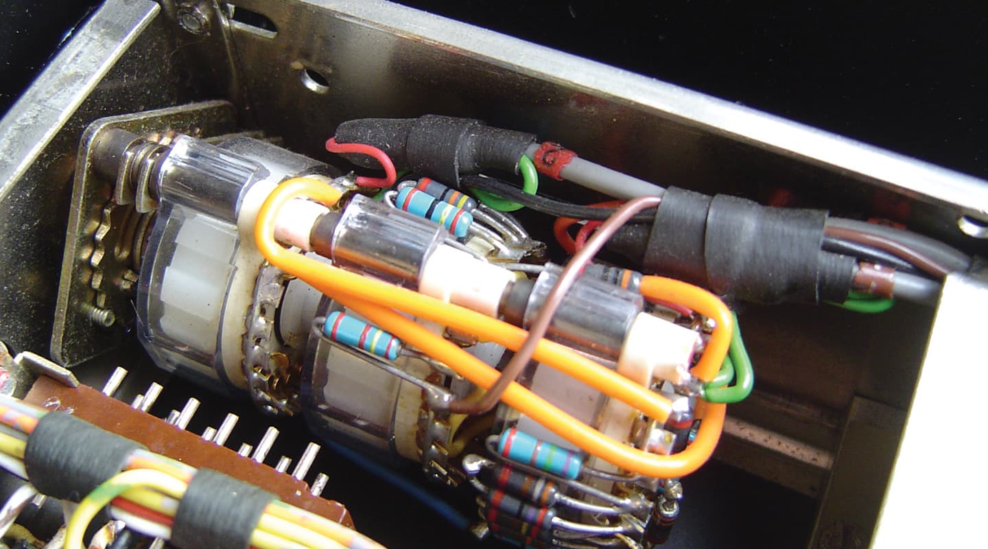
A later approach, particularly taken up by Neve, was to use a number of amplifier stages that could each have their gain adjusted over a small range, and, within that range, meet the designer’s technical aims for noise and distortion. Using this approach, the total gain of the preamp is achieved through combining the number of amplifier modules switched into the signal path, the gain of each module and the use of attenuation pads. This carefully orchestrated combination preserves headroom through all amplifying stages and keeps noise and distortion at a minimum. When a low gain setting is required, a whole amplifier unit can be switched out of the signal path, thus minimising the amount of electronics the signal is required to travel through. To achieve a smoothly stepped range of gain settings with a single gain control requires a well-engineered multipole switch. This explains why the gain control switch of a Neve 1073 is so physically large and complex looking… there’s a going on (see the photo of a ’70s Neve preamp gain switch above). Well implemented, this is a very good way of controlling gain.


LATE GAINS
Later methods of gain control arose as single amplifiers were developed that could produce a large range of gain, while maintaining satisfactory technical performance throughout. Typical examples of these are the API 2520 and the Quad Eight AM10 amplifiers. These are examples of discrete operational amplifiers (op-amps) – by far the most common amplifier topology used in audio equipment today. An examination of operational amplifiers could occupy an article within itself; indeed I have whole books that deal with the topic. For our purposes here, it’s sufficient to note that operational amplifiers have two inputs and one output. One input is in phase with the output and the other input is out of phase with the output. The amplifier itself has a very high gain, typically in the order of 100dB. When this amplifier is implemented as a preamp, some of the output is fed back to the ‘out of phase’ input. This feedback reduces the gain of the amplifier, and if the amount of this feedback is made variable, say through a potentiometer, then we have a variable gain amplifier. Typically, a range of gain of 20 to 60dB is easily achieved. The added benefit of this preamp design is that, as the feedback is increased and the output is reduced, the noise floor is lowered along with it. At low gain settings the noise floor is lower, and as the gain is increased the noise floor rises proportionally along with it.
Probably the most common microphone preamp topology found today utilises a simple pair of transistors implemented with variable gain feeding an IC operational amplifier. With good low-noise transistors running with variable gain in Class-A, and an Integrated Circuit (IC) op-amp, a microphone preamp can be built for a couple of dollars. You’ll find preamps along these lines in most consoles and other units with integrated mic preamps.
HEADROOM CHARACTERISTICS
Gain control and the basic principles of ‘headroom’ go hand in hand. There are plenty of ways to get all the gain required in a preamp, but fewer ways to do it without compromising headroom or noise performance. ‘Headroom’ is tied, in part, to the voltage supply rails the unit employs, but wherever more than one amplifier stage is employed, careful consideration needs to be given to the gain and noise relationships of each amplifier stage. Given the dynamic range of many sources, a poorly designed preamp can still overload on peaks while the gain control is set to give the average desired recording level. Just as with a chain of outboard, it’s easy to accidentally overload a unit in the middle of the chain, while still maintaining a suitable level at the end. The same mechanism can occur within a preamp itself. However, within a preamp there’s no opportunity to get your hands on the middle of the chain and make the required gain adjustments to clean things up. This dynamic headroom is often one of the characteristics that sorts the wheat from the chaff.
TRANSFORM IT
In Issue 55, ‘On The Bench’ looked specifically at transformers, and without doubt one of the most distinguishing characteristics of microphone preamps is their use (or otherwise) of an input transformer. Many designers would agree that the use of an input transformer contributes significantly to the sonic qualities of the preamp as a whole. Transformers add harmonic distortion with a unique frequency dependence; less distortion at high frequencies and more at low frequencies. Transformers will also naturally roll off very high or supersonic frequencies.
Transformers also serve perhaps one of the most important functions required in a microphone preamp – input balancing. A microphone that requires lots of amplification is a good candidate for picking up extraneous noise – in the cabling, mains frequency hum and radio frequency interference. This interference is picked up equally in the hot and cold conductors of good audio cable (oops… here come cables…) and we require the balanced inputs of the preamp to amplify the difference on the hot and cold cables (the microphone signal) and reject the common mode signal (the cable-induced interference). Transformers are great at this. Their limited supersonic and characteristic response filters out radio frequencies, meanwhile intrinsic balancing nulls out the hum. Best of all, this all happens before the signal gets into any amplifier stages.
Transformerless preamps, on the other hand, can be designed to have very good common mode rejection but do require very well balanced sources (microphones) and cabling to achieve their best rejection of common mode interference.
Although a transformerless preamp inevitably saves on costs and space – transformers are expensive and large – it can still offer a very high level of technical performance – both low noise over the full gain control range and very wide frequency response. Frequency responses out to 100kHz are not uncommon, so recording for bats is now possible!
This extended frequency response aspect is an interesting one. Perceptions run along two basic lines: that preamps which provide a sense of ‘air’ and ‘openness’ are generally transformerless, while ‘warmer’ or ‘thicker’ sounding preamps generally involve transformers in the circuit (and a response of say –3dB @ 30kHz)
The 1176, with a maximum of +40dB available between the input and output level controls, can easily provide sufficient gain
OTHER PREAMP OPTIONS
Of course, there are few other things we usually require on a microphone preamp besides a gain control. Pad, phase reverse and phantom power are other common ingredients. Most transformer-based mic preamps feature a pad, typically providing 20dB of attenuation before the signal hits the transformer. Unless the input transformer is specifically designed to handle very large signals – and this would also require it to be physically large – the pad is employed to attenuate the signal first, to prevent saturation and gross distortion within the transformer itself. Most transformerless preamps with a minimum gain of around 20dB also offer a pad to deal with particularly hot signals. Indeed, the simple maths show that if we engage a 20dB pad and then dial up 20dB of gain we are achieving overall unity gain, or a gain of 0dB, and we could reasonably expect to be able to inject a line-level signal into the preamp. This illustrates how ‘hot’ microphone signals can, in fact, be. It’s quite possible to approach near line-level signals from a condenser mic on a loud source, and being aware of this presents an opportunity to create another mic preamp option in your arsenal. Many line-level outboard devices have enough gain available to provide sufficient gain to function as a mic preamp with the right mic on loud sources. So next time you put a tube condenser or dynamic mic on the kick drum, try running it straight into an Urei or UA 1176, for example. The 1176, with a maximum of +40dB available between the input and output level controls, can easily provide sufficient gain. And you will still be able to tickle the compressor’s gain reduction with judicious balancing of the input and output level controls.
PHANTOM MENACE
You’d think phantom power would be straightforward, whereby 48V is fed to microphones requiring it. However, it’s surprising how many manufacturers skimp in this area and provide an inadequate phantom supply that buckles under load. Some condenser mics draw close to the theoretical maximum of 14mA available to a microphone through the phantom supply resistors. Under this kind of load, the phantom voltage drops out of regulation and becomes full of hum and buzz.
The provision for phantom power also places a limitation on the maximum input impedance of the preamp. In recent times, many designers have begun to take advantage of the subtle tonal changes available by offering a variable input impedance.
This input impedance is all about the load that the microphone ‘sees’ and how that load affects the output of the microphone. This affect is most significant with microphones that employ an output transformer. Phantom power is delivered to the microphone through the agreed standard of 6.9kΩ resistors, one feeding the hot and one the cold of the preamp’s input socket. These resistors are present regardless of whether the phantom power is turned on or off and place a load on the microphone, thus determining the highest possible input impedance that the preamp can achieve. These resistors on their own would yield an input impedance of 13.6kΩ. In practice, it will be much lower than this when other circuit impedances are included. However, there’s good evidence for the sonic benefits of quite high input impedances for ribbon microphones. The input impedance of most preamps is around the 2kΩ mark. A variable input impedance that ranges higher and lower than this can take a mic from open and airy to dark and warm – a neat trick implemented with a minimum of passive parts.
HITTING THE HIGH-PASS
High-pass filters are a very useful tool, whether available as part of a mix level EQ process, or incorporated into a mic preamp. Cleaning up low frequency garbage (noise, room rumble, trucks on the highway) can significantly assist in gaining clarity in a final mix. By placing a high pass filter within the preamp itself this ‘cleaning up’ can be done in the tracking phase: less to think about later, and as they say, commitment is a good thing! There is wide variation in the facility provided in high pass filtering, ranging from simple passive filters at a fixed frequency to a continuously variable frequency with a steep filter slope. To achieve a rate of cutoff or slope greater than 6dB per-octave – typically 12- or 18dB per-octave – additional amplifier circuits are required to provide active filtering. A good filter design will allow complete bypassing of these additional circuits when the high-pass filter is de-selected. Using a simple combination of a resistor and capacitor (and no additional amplifier circuitry), a 6dB per-octave slope can be achieved. Although the cutoff rate of this design is low, the sonic impact is minimal in the pass band.
A quirk of some of the sonically interesting high-pass filters is that they create a small amount of boost in frequencies just above the cut-off frequency. This has the perceived effect of restoring a sense of ‘weight’ back into the sound while still achieving low-frequency attenuation. One aspect of high-pass filters to always keep in mind is that, like all analogue filtering or equalisation, not only are the volumes of your chosen frequencies altered, they’re also phase shifted. With any high-pass filtering there will be small amounts of phase shift occurring into the pass band above the cut-off frequency, and different filter designs will induce different amounts of this phase shift. You have been warned.
While it’s no longer difficult, nor particularly expensive, to build a high quality microphone preamp from a technical perspective, there is still plenty of scope for a designer to explore the nuances. In selecting a mic preamp for a particular job we’re all seeking that successful marriage of mic to preamp in order to yield the desired representation of the sound we’re capturing.
Happy hunting!


RESPONSES