

On The Bench: Impedance
Ohm m’goodness, you’ll finally know what impedance actually means after you’re finished here.
23 April 2007
Text: Rob Squire
One of those terms we often come across in the audio world is the word Impedance, often quoted as one aspect of a piece of equipment’s technical specifications. Typically quoted is a unit’s input impedance and output impedance. So, what is it and what does it mean?
Impedance is technically a measure of a device’s opposition to the flow of current in a circuit delivering AC (alternating current) signals… and audio is an AC signal. It’s specified in Ohms (Ω) and consists of a combination of the resistance, capacitance and inductance of the device [see sidebar for more on these other electrical terms]. Since it includes frequency-affecting capacitance and inductance this makes the value of impedance, strictly speaking, dependant on frequency. Thus the impedance of a device will vary with frequency and can’t be expressed with just a simple number. In fact, the expression for impedance would be a fairly complex mathematical equation.
Fortunately for us, across the audio bandwidth of 20Hz to 20kHz the typical capacitances and inductances that we find as a part of the input or output circuitry of most equipment – and indeed cabling – are small enough to be ignored when it comes to establishing impedance. We can then just examine the resistances of the circuits involved and approximate our expression of impedance to the resistance of the circuit. And since resistance is not frequency dependent we can have a simple number rather than a complex frequency-dependant equation.
PAYING OHMAGE
For those with a penchant for vintage equipment we often see a unit’s input and/or output impedance specified as 600Ω. This harks back to standards developed by the telephone industry and arises from the characteristic impedance of very long telephone lines, where a pair of widely spaced wires has itself a characteristic impedance of 600Ω. In the early days when equipment was limited, what was important was the transfer of power. With output devices, cabling and input devices, the most power is transferred when all the impedances match, i.e., the output impedance matches the cable impedance, which matches the receiving input impedance. This set a historical precedent, where 600Ω became the standard input and output impedance for audio equipment, which was strongly adhered to in the broadcast industry and really only began to weaken in the 1980s. (Until then most equipment had an output and input impedance of 600Ω.)
When output and input impedances are the same and connected together we have a ‘matching impedance connection’. Today the concept of matching input and output impedances still arises as a result of this historical application, but is, in fact, something of a misapplication with modern equipment. Shortly we’ll see why.
When an input impedance is matched to an output impedance, while we get maximum transfer of power, we also lose half the voltage – a loss of 6dB. Effectively the output impedance and input impedance form an attenuator. [See Fig.1]

And, with matching impedances causing this 6dB drop in level, it was obviously important that all the specified impedances were in place when setting levels, as a chain of equipment designed for impedance matching could end up losing or gaining 6dB if care wasn’t taken.
Today, however, the approach taken with the interconnection of audio equipment is not to match impedances but rather to use the concept of ‘bridging’ impedances. Strictly speaking, a bridging impedance is one where the input impedance is at least 10 times greater than the output impedance. Most equipment today has a low output impedance of typically 30 to 100Ω and a medium to high input impedance of 10,000 to 47,000Ω. This results in maximum transfer of voltage with minimum current flowing. [See Fig.2]

In this example the attenuation caused by the low output impedance and high input impedance is only 0.08dB.
Generally we can see that with the typical input and output impedances used today there is very little loss of signal level nor any particular care required when connecting devices with regard to their impedances and subsequent change of level. Indeed we can see that the use of low output impedances and medium to high input impedances allows us to have one output driving two or more inputs with little loss of level.
Remember the historical origins of 600Ω actually came from the characteristics of spaced cables used for transmission of telephone audio. This reminds us that cables also have an impedance value. Typically, for the sorts of lengths of cable used around recording studios we can largely ignore the affects of cable impedance, with perhaps the exception of the cables’ capacitance (its resistance and inductance are negligible). Most balanced audio cable has in the order of 150pF [Pico Farad] per metre of capacitance between conductors. This, combined with the output impedance of a device driving the cable, forms a low-pass filter [see Fig.3]. For example with a 100Ω output driving 10 metres of cable, the –3dB point is greater than 2MHz. So, unless we go to very long cables or high output impedances the rollover frequency is well outside the audio band. Even in an extreme situation of, say, a microphone with an output impedance of 200Ω (not usual) driving 100 metres of cable we still get a frequency response that is only –3dB just above 100kHz. Thus we can see that with typical output impedances found in modern equipment and reasonable cable lengths we have no trouble in delivering full bandwidth audio, even a dog would be happy.

The combination of the resistive output impedance in series with the audio path and the capacitance of the cable in parallel or across the audio path forms a low-pass filter.
For those with a calculator handy the –3dB point is given by the equation:

One situation where cable does affect frequency response is with passive electric guitar pickups. A guitar pickup is essentially a coil of wire around a magnet. By coiling wire we make an inductor so the impedance of a guitar pickup can’t be simplified to a resistor and is a complex combination of resistance, inductance and capacitance. Which means its impedance is very frequency dependent and is generally fairly high across the audio band. There is wide variation in the impedance characteristics of different pickups but typical values are 30,000 to 80,000Ω at 10kHz. A typical guitar cable will have about 150pF of capacitance per metre thus the effective low-pass filter formed through the combination of the pickup’s output impedance and the cable’s capacitance can result in a 14dB loss at 10kHz with a 5m cable. This explains the loss of tone we get out of electric guitars with long cables (unless they have active pickups, which provide a low and frequency-independent output impedance).
The trick, when you do want a long cable run for electric guitars, is to not use standard guitar leads but good quality, fully-shielded antenna cable. Antenna cable typically has about a third of the capacitance of guitar cable, meaning you can get a longer run for the same amount of high-frequency loss. The downside is that antenna cable is usually pretty stiff and won’t play happily on a stage but can be ideal in a fixed installation in a studio, say between a control room and studio or isolation room.
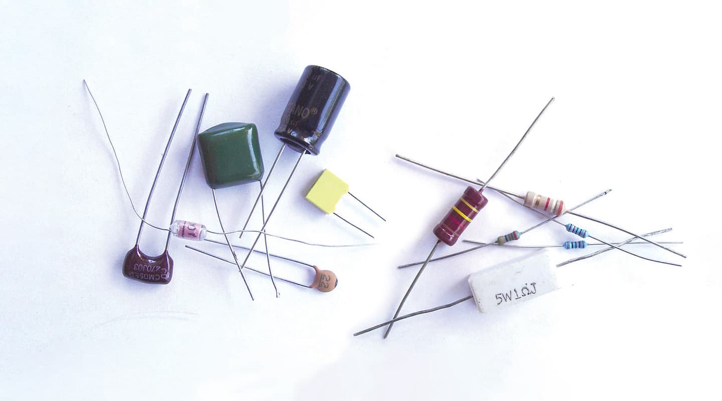
Resistors

Capacitors

Inductors

In the world of electronics, three fundamental qualities (resistance, capacitance and inductance) are realised in three fundamental components: the resistor, capacitor and inductor. Let’s take a closer look:
Resistance: a measure of the degree to which a device opposes the flow of current. The ubiquitous Ohm’s Law spells this out for us: R (resistance) = V (voltage)/I(current).
Ant Hill Mob Busted: The most bizarre thing happened when I was taking those photos. I’d dumped the resistors down on a sheet on paper on the ground outside and as I got the camera lined up, this ant walked across the paper, grabbed one of the smaller resistors and dragged it off the sheet of paper and into the garden. It then let go and walked off, obviously after realising it was the wrong value part for the Fairchild clone the workers were putting together back in the nest!
Capacitance: a measure of the amount of electric charge stored. Capacitors are devices that can store charge, and are mostly found storing charge in power supplies. They also possess a frequency-dependent behaviour, where at DC (zero Hz!) they act like an open circuit but with AC signals their effective impedance lowers with increasing frequency allowing more current to flow.
Inductance: a measure of the magnetic flux produced by the flow of current in a conducting material. A practical inductor usually consists of a coil of wire and has the quality whereby the change of direction of current flow with AC signals produces an opposition to that flow of current. At DC they behave like an ordinary piece of wire but with AC signals their effective impedance increases with increasing frequency.
It is the frequency dependent behaviour of capacitors and inductors that makes them useful in constructing filters and EQs, although inductors are not used much any more, being replaced with active electronic circuits. (A bit of a shame really, think of some of the classic EQs that used inductors – Neve, Quad Eight, Pultec – perhaps there’s something in their imperfections that contributes to a sound we fancy!)
MICROPHONE IMPEDANCE
Another application where impedance can make a difference is in microphone preamps. Many microphones have transformer-coupled outputs. With a condenser microphone, especially a tube-based mic, the transformer is stepping the audio from the primary side down to the secondary (or output) side. The transformer literally transforms the impedance of the microphone’s internal amplifier from a high impedance with a higher signal level (but poorer ability to drive long cables), to a low impedance, with lower signal level but better ability to drive long cables. The greater the ratio of this transformation, the more susceptible the transformer is to deviations in frequency response, often exhibiting a rising frequency response at higher frequencies. This effect can be modified by placing a load on the output of the transformer, this load is effectively the input impedance of the microphone preamp to which it is connected.
Microphone preamps have input impedances that range from 600Ω to 2,000Ω. Changing this input impedance can have a subtle effect on the frequency response of a particular mic. There are no rules here and some manufacturers have started producing mic pre’s with a variable input impedance – either a switch that selects between a couple of different values or a continuous control. One technique of altering the input impedance of transformer-based mic preamps is to provide two separate input or primary windings on the transformer and connecting them in different ways. If the windings are connected in parallel you get a lower input impedance and more gain from the transformer, while if connected in series you get a higher input impedance and less gain. This technique was employed in the Neve 1073 module mic input with a Hi/Lo switch (inconveniently) located on the rear of the module! One thing that arises from this method is that the change in gain from the two switch positions tends to overshadow the subtle change in frequency response that you may be getting from a particular mic, making quick A/B assessment difficult.
Ribbon microphones also have transformers in their outputs, however, in this case, they are stepping up the incredibly low voltage, low-impedance output from the ribbon motor to a higher voltage output presented on the mic’s socket. And you thought ribbon mics already had low output! Without this transformer, the output would be another 30dB lower! Ribbon mics have a very high ‘turns’ ratio and thus can be significantly affected by the input impedance of the mic pre. Often an input impedance of greater than 10,000Ω yields an improved tonality. Unfortunately this is an input impedance much higher than most preamps provide.
ALL IMPEDA-MENTS SIDE
The days of matching impedances seem to be well behind us. We don’t run cables over vast distances, in fact, over the kinds of cable lengths the vast majority of us use these days – at least for line level interconnection – most equipment plays happily together and presents no particular impedance-related issues. However, transformer-based equipment and very high-impedance sources, such as guitar pickups, do still require us to pay attention to how we connect them up.


RESPONSES