


ROOM PENETRATIONS: THEIR TREATMENT & MANAGEMENT
14 April 2014

Every studio needs them, but how do we stop room penetration points – doors, windows and air-conditioning ducts etc – from destroying the isolation integrity of our studios?
Text: Greg Tailby
If you’re one of those AT readers who’s lucky enough to be preparing to embark on your own studio design and construction soon, whether it be at home or elsewhere, it’s critical to understand the two fundamental aspects involved in designing a decent acoustic enclosure. One of these is ‘isolation’ of the space from the surrounding environment, the other is its ‘sound field’ aspect: how it sounds inside that enclosure.
The overall design of your new space must combine an understanding of these two fundamentals, not just one or the other – a common mistake many people make. Your new space can’t simply be built like a bomb shelter; be great at preventing sound from escaping or penetrating the space, but sound truly awful on the inside. Nor can your new space be fantastic sounding on the inside and yet hopeless at keeping sounds in and out. Understanding how these two requirements of your studio knit together to create a productive and inviting workspace is the real trick. So let’s explore these two concepts further shall we?
IT TAKES TWO
I generally refer to the two aforementioned fundamentals of acoustic enclosure design as the ‘sound treatment’ and ‘isolation treatment’. If you like, they’re the Yin and Yang of any good studio design. The Sound treatment is all about what we need to do to the inside of the room to make it sound good, while the isolation treatment refers to what we need to do to stop the room from leaking sound into the outside environment, or having it leak in.
It’s a tricky undertaking building a studio space. There’s so much we need to ferry in and out of a studio – people, air, power, light, heating and cooling – that by the time it’s all said and done, a badly designed studio space can often look more like Swiss cheese than an acoustic enclosure, and being full of holes isn’t exactly conducive to good sound isolation. So how to we solve this conundrum?
INSANE IN THE MEMBRANE
There are umpteen products and techniques that can be used to address the issues involved in providing the actual sound barrier (membrane) to the enclosure, depending on your budget and sound transmission loss (STL) requirements. However, once you put a hole through this membrane – no matter how small – the vast majority of your isolation is lost… The key to a successful outcome is to plan ahead and incorporate these necessary elements into the overall design. If you don’t – if you turn a blind eye to them and forge ahead without a plan – you’re going to come unstuck.
The isolation treatment (for sound loss through a ‘penetration point’ in your membrane) is based on the understanding of some basic facts about sound. Firstly, sound doesn’t travel well around corners. Secondly, and perhaps most fundamentally, sound loses energy over distance and through friction if exposed to fibrous material. (Fibres vibrating against each other convert sound energy to heat).
Making a penetration point airtight is arguably the most effective method to employ… but also the most theoretical. In practice, it’s actually very difficult to achieve an airtight seal on something designed to open and close umpteen times a day. What’s worse, until your enclosure is finished it’s hard to test for its success or failure and – if there’s an issue – it can be expensive and sometimes impossible to treat. These basic principles inform our approach to treating the problems involved in building a successful acoustic enclosure.
THE GREAT ESCAPE
The most effective way of dealing with escaping sound is to position a penetration point at a location where there’s a large cavity or corridor behind it that can act as a backstop – think of it like the wicketkeeper behind a fast bowler. Commonly referred to as an ‘airlock’ or ‘sound lock’, this cavity is then treated with fibrous material on its surfaces to absorb the sound. Rather than trying to prevent the sound escaping through the penetration point in the first place – a practical impossibility in most cases anyway – it’s far more effective to manage the escaping sound energy by dissipating it within this extra space – ramming the soundwave into all that absorbent material and guiding it through all that air. But as you may have already surmised, this treatment option often takes up far more space than if we’d simply stopped the sound more effectively back at the penetration point, so you’re probably already asking yourself: ‘ what other less space consuming options are available to me that I can incorporate into my design?’
FLOATING FLOORS
If your enclosure is to have a ‘floating’ floor (one that’s decoupled from the enclosure) – and it should – this is an excellent point at which to make a penetration for cabling. Apart from the fact that it minimises clutter by bringing the cables up through the floor only where you want them, it’s inherently far more soundproof provided the sub-floor is sound insulated, as Figure 1 demonstrates.

FIGURE 1: Cross section of a double-layer floor sitting on timber batons decoupled from a concrete slab on neoprene pads (floating floor). Sound travels through the penetration and reflects between the slab and floating floor, passing through the absorption material at each reflection, thus losing sound energy.
In this diagram above, sound goes through the hole in our floor and into the absorptive material below, which immediately soaks up some of the energy. The remaining energy is then reflected back up off the concrete slab and into the underside of the floating floor, whereupon it’s reflected back down into the absorption layer once again, absorbing yet more energy. This happens repeatedly until the soundwave is eventually killed off – converted almost entirely into heat energy.
Below is a diagram of the audio and data cabling layout at Nut and Butter Studios in Marrickville, Sydney (see Figure 2). These penetrations are far enough from the walls to allow the absorption below the floor to reduce noise energy before it reaches the wall cavity.

FIGURE 2: Floor plan of two enclosures within a room showing floor penetrations and cable layout. Notice the use of bends and turns in the cable pathway, taking advantage of the fact that sound doesn’t travel around corners well and dissipates over distance.
Because the cable pathways don’t have much in the way of absorptive material inside them, if they were straight they’d simply provide an escape tunnel for the sound. Not good. To combat this we’ve introduced bends and turns into the cable pathways, to create a longer, more complex passageway that soundwaves find difficult to navigate their way through, and thus dissipate into heat energy before they can escape. This is all quite straightforward to design, but of course laying cables isn’t and this technique also demands that you use more cable. The trick is to balance the need for short cable runs with the demands for sound isolation. Cables also need to be laid flat and parallel to each other whenever possible, and be relieved of tension so they stay where they’re laid and not crossed over each other. You need to take your time with this procedure as it’s easy to accidentally couple your floating floor to the sub-floor via a tightly fitted cable installation, which can ruin the isolation you’ve fought hard to achieve. The following photo (Figure 3) shows cables properly laid and intersecting at the point where they will come up through the floor.
See figure 3.

FIGURE 3: You must take care that your cabling is laid correctly to avoid coupling your floating floor to the sub-floor.
BAFFLED
A more involved penetration is typically the one you drive through a wall. Figure 4 (below) shows plan and elevation drawings for a baffled penetration point that uses the wall studs and noggins as the frame of the box itself.
See figure 4.
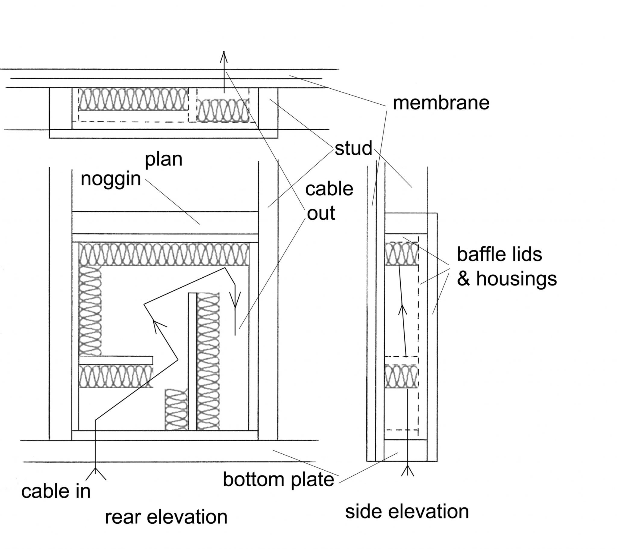
In this example, the cabling comes up from under the floor, into the baffle at the lower left corner, winds around the box and out through the membrane of the adjoining room. Notice the ‘in’ and ‘out’ points are situated on different planes – meaning that the sound is made to work hard to find its way out through the maze of twists and turns inside the box, rather than being given a direct line-of-sight path through the wall. And, of course, the harder the sound has to work to get through, the weaker the sound wave will ultimately be. Curiously, it’s more effective to only partially fill the box with absorbent material by only covering one face of each parallel surface with absorbency. This allows more surface area of absorption rather than creating a tunnel through the baffle.
SPLIT-SYSTEM AIR-CONDITIONING
Isolation of penetration points for split-system air-conditioning is another common concern for studio owners – one that basically involves the same issues we’ve just dealt with in relation to cabling. There are, however, a few extra issues to consider, one of which has a simple and somewhat surprising solution. Air-conditioning units have a waste pipe for condensation, which typically consists of a tube, so even if you run it through baffled boxes and create bends, sound energy will generally still travel through it. This can be overcome, however – to a reasonable degree at least – by putting a p-trap in the line (just like the one in your toilet that stops bad smells from coming back up the pipe). This blocks the airflow through the tube but still allows the water to drain away. The pipe is quite narrow so we’re not talking low frequency transmission here, but there are still some higher frequencies to contend with. If the isolation is insufficient, the waste pipe should terminate in a cavity, such as a bathroom for instance, which has fibrous material fitted to opposing surfaces, as discussed earlier.
The other important consideration is the transmission of vibrations through the coolant pipelines. It might seem insubstantial, but if hard-fixed to your room, or if they make contact with your isolation box, coolant pipes will set up a mechanical resonance loop that will be sympathetic to a room frequency and this will ultimately boost the level of that frequency in your room.
Finally, there’s also the small issue of maintenance, inspection for leaks and the ability to fit the fan unit to the tubing. Most designs or air-conditioning systems in studios fail to incorporate the basic ability to inspect the system once it’s installed, and this can cause untold problems in the future. Figure 5 shows a sketch of the isolation units we designed for Nut and Butter Studios that incorporates access ‘lids’ into the design, allowing for future access.
See figure 5

FIGURE 5: Plan and elevation drawings for a ‘split system air-conditioning’ baffle. The diagrams above show condenser pipes only for simplicity, but your electrical cabling and waste pipe would also follow this pathway. You must allow enough clearance through the baffle to ensure the pipe doesn’t touch the box to avoid mechanical resonance. Notice also that there is ‘fall’ on the pathway to allow the waste to drain, which must be at least 50mm per metre of pipe.
Basically the only difference is that the lids for the back of the box are sealed in place with neoprene gaskets rather than sealant. This enables the lids to be screwed on and off whenever the air-conditioning needs to be inspected for whatever reason.
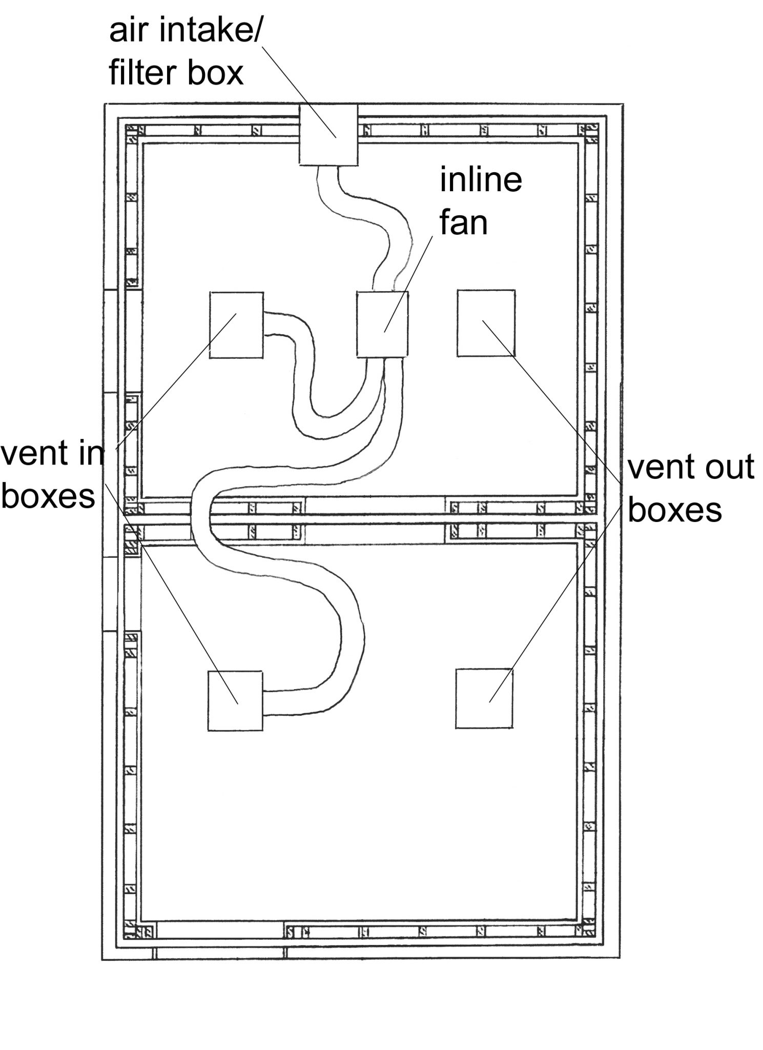
FIGURE 6: A very basic fresh air system installation utilising the cavity of a gable roof. Its simplicity is enabled by the fact that the cavity is above the enclosures and that they share the cavity. The air intake therefore doesn’t require isolation treatment and the two enclosures can utilise the one system.
FRESH AIR SYSTEM
Figure 6 shows the layout for a fresh air system in the roof space of Nut and Butter Studios. Here the system is comprised of the air intake/filter box, which sucks air in from outside the building. This is ducted to an in-line fan which then splits off to our vent-in baffled boxes (shown in Figures 7, 8 and 9) via as much acoustic ducting as we could fit into the space in a snaking pattern. The vent-out boxes are placed as far away from the intakes as possible to maximise the ventilation of the rooms and these vent out into the treated roof cavity. They’re also far enough away from the aircon that the cooled/heated air doesn’t go straight out into the roof cavity. It’s very important that your air-conditioned air flows through the room to cool it before it finds its way out again, otherwise all you’ll end up with a poorly air-conditioned room and an enormous power bill.


FIGURE 7,8 & 9: The side view of the interior of the vent box baffles shows the 300 x 50mm pathway through the box with the absorption placed in a way that doesn’t defy gravity. It’s still glued because it will eventually come unstuck if placed in a hanging position.
It’s probably not necessary to use absorptive material on both side walls as shown – the pathway for the airflow is so complex the tunnelling effect doesn’t exist and it adds slightly more surface area absorption.
Although the vent-in and vent-out boxes are the same design and the installed vent-out box shown in picture is with the fronts fitted, the vent-in boxes require a simple sheet metal cowling/adaptor to connect to the type of acoustic ducting you decide to use.
DOORWAYS
Doorways are definitely the most vulnerable element in your studio and perhaps the best example of why solutions for these penetration points are best described as ‘treatments’ rather than ‘cures’. It’s not just about having a sound proof door. There are many issues involved: the rigidity of the door, door frame and wall; having such a big hole in it; whether you need a window; the floor at the doorway; the door catch and light switch.
There are many types of door construction and door seal systems around these days, but a great system I use repeatedly is one that was designed by BBC engineers and used in their studios all over the world. This system utilises a door with an absorbent edge that reduces sound energy as it passes between the door and the door frame. Most other systems attempt an airtight seal, which, from experience, fails as soon as there’s any movement in your room or door. If you were relying on these seals you’d have to adjust them every time you needed maximum isolation. Nothing I’ve seen can tolerate that frequency of adjustment and it’s a difficult (not to mention time consuming) activity.

FIGURE 10: The ‘absorbent edge’ door sub-structure, ready to fit the other door skin: All the joins must be caulked with sealant to contain the sand that fills the cavities once the door is hung.
Figure 10 (above) shows a photo of the sub structure of the ‘BBC doors’ concept. The timber is just rough sawn 4×2, set back 70mm from the door edge. This creates a space to fit the absorbent material when the other door skin is fitted, as show in Figure 11. All the sub frame timber must be sealed against the door skins and at all the joins, so it can be filled with kiln-dried sand once the door is hung. This adds mass to the door, which increases its sound transmission loss (STL). Figure 10 also shows the hinge blocks, which are housed into the back of the 18mm ply faces for maximum strength to cope with the weight. We also use a drop seal at the bottom of the door instead of the absorbent edge, because A: it tolerates a lot of door/room movement and B: it’s airtight, so if we find we need extra isolation, we can add the airtight perimeter seals later, without having to take the door off again to complete the seal. Figure 12 shows the finished hanging door with perforated edge trim and bottom seal fitted.

Figure 11
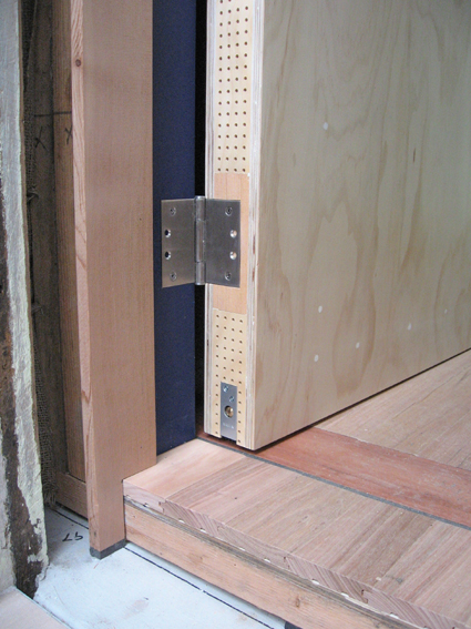
Figure 12
The construction of the doorway opening is shown in Figure 13. Double wall studs are used on each side of the door opening to compensate for the loss of structure in the wall from making such a big hole. The room membrane then continues around to form the door frame. Where the sheets butt together, we leave a 5mm gap, which we then fill with a sealant. This is copying the actual room membrane technique. The reason for a gap of this size is that the sealant will retain its integrity with movement of 20% either way. That is, it will stay sealed if the gap shrinks or expands by 1mm. That seems to be enough from my experience. It’s a lot of material, which is why the gap is only 5mm, You could of course have a wider join, but this will invariably cost more in terms of sealant. At Blackfoot Sound in St Peters, Sydney I think we spent around $2000 on sealant alone, so it’s no exaggeration to say that every extra millimetre you incorporate into the design becomes pricey.

Figure 13
BUT WAIT, THERE’S A CATCH
Unless you’re intending to design a ‘Star Trek’ type door that slides open and shuts with a hiss of hydraulic seals you’re also going to need some sort of door catch. In my opinion, electro-magnetic fire door catches are definitely the way to go for studios and work well with this particular door construction. The beauty of magnetic catches is that there’s no penetration point through the door itself, and the magnetic catch is on the outside of the frame, so the power cable penetration is outside also. There’s a push button opener both inside and outside the room with only the inside one requiring isolation treatment.
Figure 13 also shows the treatment for the door and light switch penetrations. The same principles apply here as with our wall penetration discussed earlier in Figure 4. The only difference being that we drill the hole diagonally through the membrane, continuing through the sub frame of the doorway and into the area between the studs and noggins. As with all your isolation boxes, lids, and the second layer of board on your boxes, we maintain the room membrane technique of allowing gaps and filling them.
Run the cable into this box and out through the noggin at the top and up to the roof cavity (ie, on a different plane) as far from the entry point as possible. I like to seal these penetration points as well, by routing a channel in some board – about 10mm deep – and fitting it over the back of the hole with the cable running along the channel and out at the end. Fix this by using heaps of sealant and screws so it oozes out everywhere. Then treat the inside of the box with absorption and fit a lid. The lid should be 5mm undersized all around, and be bedded to the internal frame with sealant, screwed and then caulked. It all seems pretty over-the-top, but what we’re actually doing here is effectively adding an extension to the room. The only point where we want leakage is where we want it to leak!
POWER THROUGH THE PEEPHOLE
Typically when I build a studio for a client there’s a roof cavity to work with, and in my experience the roof is the obvious place to lay all the power cables for the studio. It’s neat, allows future access and is quick because there’s very little in the way or fixing required. It also keeps your power away from your data and audio cable where it might otherwise cause interference. The vent-out boxes are a good place to run the light power if you’re using them, otherwise, I generally build boxes within the rafters like the wall iso boxes. As the rafters invariably deeper than the wall stud, you end up with bigger boxes, which is a bonus. The bigger the box, the better the absorption. We only need one penetration per room for the power as we run it in a chain around the inside of the room in conduit below the sound treatment equipment. Most rooms require some form of corner treatment unit anyway, and this provides a convenient and inconspicuous installation for power from the roof to the chain.
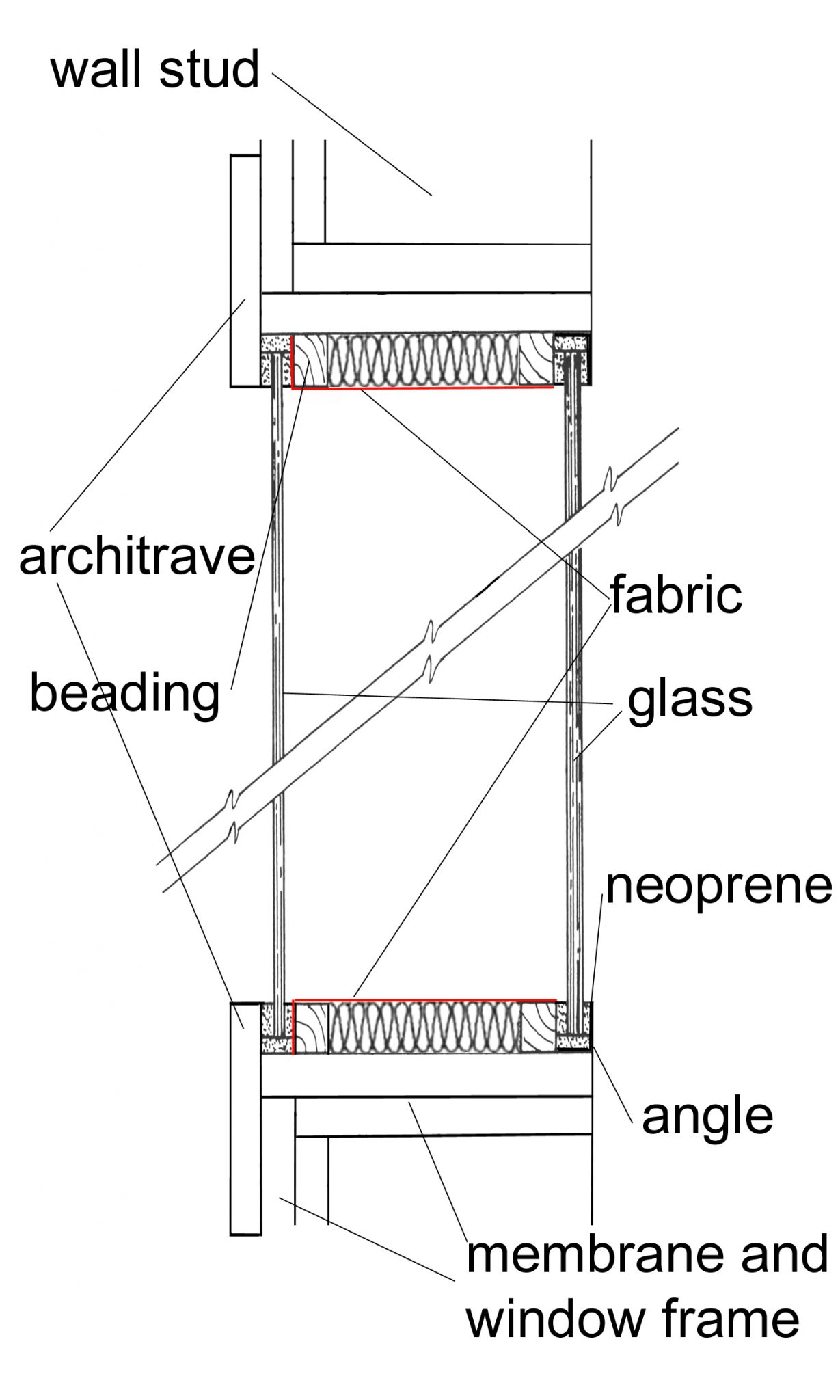
Figure 14
WINDOWS
Windows in your studio should essentially be built in the same manner as the doorways. My favourite approach is to fit two panes of floating glass within this opening creating an air-tight seal (see Figure 14). I prefer to use neoprene housings as opposed to silicon because you risk either a big mess or failure if you don’t use precisely the right amount. There are lots of factors and opinions regarding what glass thickness to use, how far apart the panes should be and whether they should be parallel or skewed, but in terms of isolation, the model illustrated here will provide sound insulation of almost 50dB by using a 6mm pane and an 8mm pane, provided it’s carefully built.
The distance between the two panes of glass must be at least 100mm to work, and distances of up to about 200mm will give you even more isolation. The absorption between the glass, around the inside of the frame discourages resonance in the air space between the two panes and contributes significantly to its efficiency. Just remember to clean the glass thoroughly before you install it – there’s nothing more frustrating than a conspicuous smudge on the inside of the glass!
BASICS OUTLINED
So far I’ve only outlined the basic principles for the sound isolation of penetrations. There is, of course, far more to it, and more specific examples of some of the principles introduced here will be explored in greater detail in forthcoming issues of AT.
The techniques discussed and examples given here have been done so with the specific intention of providing the home studio enthusiast or professional with the basic information required to achieve a successful outcome. Gaining a greater insight into what goes on behind (and between) the walls, floors and roofs of a studio is vitally important if you’re intending to embark on this sort of construction yourself. It’s sometimes easy to forget that power, data, aircon, fresh air, doors and windows all need access in and out of a studio space. Without these needs built into your design from the outset, you’re likely to be disappointed with the final outcome.
The variations on these examples are infinite, of course, but having the right approach will enable you to overcome any isolation issues that you would normally encounter. Stay tuned for more on this in future issues of AT. Until then, good luck with your design!


RESPONSES